10 Common Installation Mistakes That Ruin Submersible Level Sensors
TIME: 2026.11.19AUTHOR: OlinaNUMBER OF VIEWS 3
Submersible level sensors are among the most reliable instruments for continuous tank and sump monitoring—when they are installed correctly. In practice, most field failures are not caused by the sensor itself, but by preventable installation errors: a pinched cable, a missing vent tube, a loose gland, or a sensor sitting on the tank floor.
This guide walks through the 10 most common installation mistakes that damage submersible level sensors, shorten service life, or produce unstable readings. It is written for installers, maintenance engineers, plant operators, and instrumentation buyers who want to avoid costly downtime.
Why Submersible Level Sensor Installation Matters
A submersible level sensor works by measuring hydrostatic pressure at the bottom of a liquid column. The sensor must be fully submerged, properly vented, electrically protected, and mechanically supported. If any of these conditions are compromised, the reading can drift, fluctuate, or fail completely.
Unlike non-contact sensors, submersible sensors live inside the liquid. That makes installation quality especially important. A small mistake during mounting, wiring, or sealing can lead to long-term problems such as moisture ingress, cable damage, corrosion, or signal interference.
Mistake 1: Ignoring the Vent Tube Inside the Cable
Most submersible level sensors use a vented cable. The tiny vent tube inside the cable allows the sensor to reference atmospheric pressure. If this vent is blocked, kinked, or sealed, the sensor cannot compensate for changes in air pressure.
Common symptoms of a blocked vent tube include:
Slow or drifting level readings
Incorrect readings after temperature changes
Stable readings that do not match the actual tank level
Gradual measurement offset over time
To avoid this, never crush, knot, or tightly tape the cable. The vent path must remain open from the sensor all the way to the termination point. If the cable passes through a sealed conduit or gland, special care is needed to keep the vent tube free.
Mistake 2: Mounting the Sensor Directly on the Tank Bottom
Placing the sensor directly on the tank floor is one of the fastest ways to damage it. Sediment, sludge, sand, and debris can settle around the sensor diaphragm and cause measurement errors. In wastewater, chemical tanks, or outdoor sumps, bottom sediment is almost inevitable.
A better practice is to suspend the sensor slightly above the tank bottom. This allows liquid to flow freely around the sensing element while reducing the risk of clogging or physical impact.
For tanks with heavy sludge, consider using:
A mounting bracket
A protective cage
A stilling well
A raised platform
A suspension cable with a fixed stop
This simple adjustment can prevent false low-level readings and extend sensor life.
Mistake 3: Using the Cable as a Load-Bearing Rope
The sensor cable is not designed to carry the full weight of the sensor over long periods. If the cable is used as the only support, it can stretch, separate, or pull away from the sensor body. Over time, this may damage internal connections or compromise the sealing structure.
Always use a proper support method, such as:
A stainless-steel suspension wire
A chain with a sensor bracket
A fixed mounting flange
A cable clamp that transfers weight away from the cable
The electrical cable should carry signals, not mechanical load.
Mistake 4: Leaving the Cable Gland Loose or Unsealed
Water ingress through the cable entry point is a frequent cause of sensor failure. Even if the sensor body is rated IP68, moisture can still enter through a poorly sealed cable gland, junction box, or termination point.
Before commissioning, check that:
The cable gland is tightened to the correct torque
The cable diameter matches the gland specification
The sealing ring is intact and not twisted
The junction box cover is fully closed
The termination point is protected from rain and condensation
In outdoor or high-humidity environments, use a waterproof junction box and route the cable downward where possible. This helps prevent water from running along the cable into the enclosure.
Mistake 5: Installing the Sensor Near Agitators, Inlets, or Turbulent Zones
Submersible level sensors measure pressure at a single point. If the sensor is installed near a pump inlet, mixing agitator, filling pipe, or falling liquid stream, the reading may fluctuate even when the actual level is stable.
Turbulence creates dynamic pressure changes that are not related to true liquid height. This can cause the control system to trigger false alarms, unnecessary pump starts, or incorrect dosing.
Install the sensor in a calm area of the tank. If the tank has no quiet zone, consider using:
A stilling well
A perforated pipe
A baffle plate
A separate measurement chamber
The goal is to let the sensor “see” static liquid pressure, not flow noise.
Mistake 6: Choosing the Wrong Material for the Liquid
Sensor housing material must match the measured liquid. A sensor that works well in clean water may fail quickly in seawater, acidic wastewater, chemical tanks, or food-processing liquids.
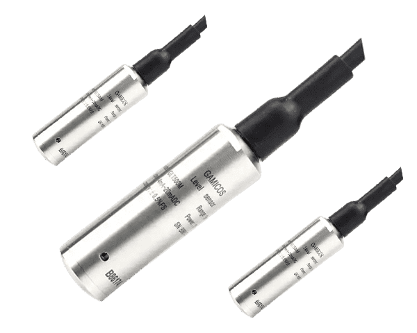
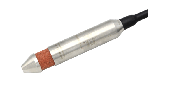
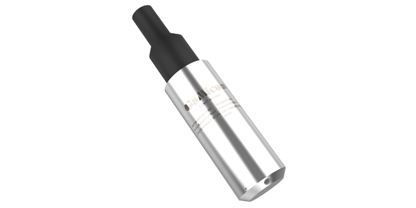
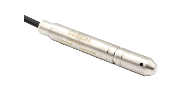
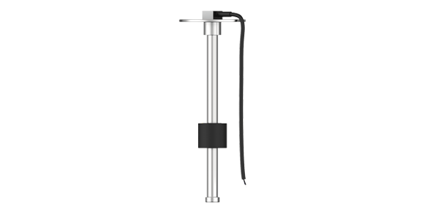
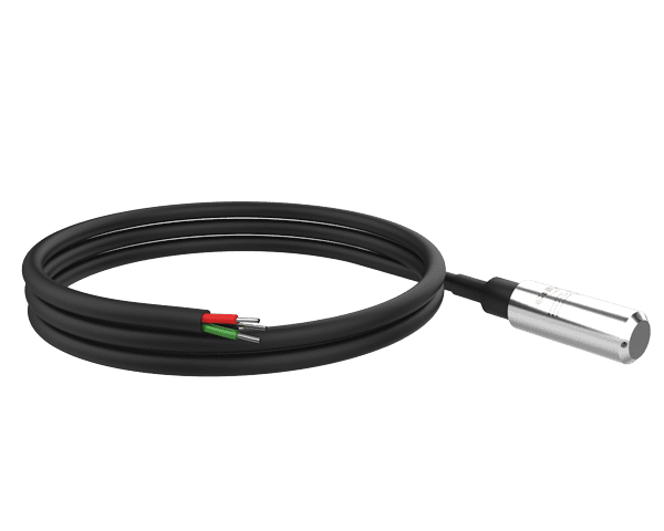
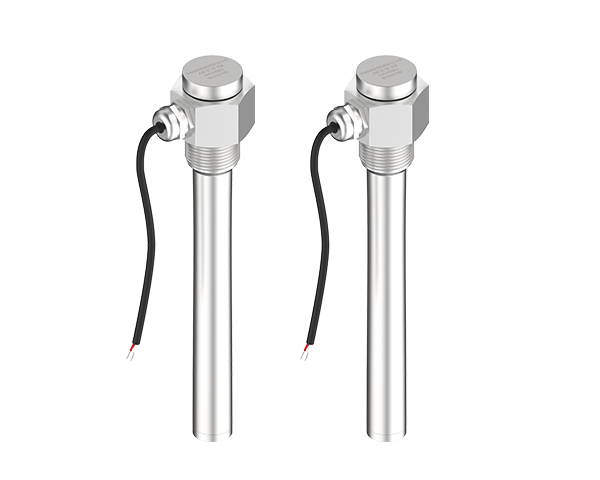
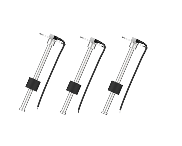
For relatively clean water, neutral liquids, or mild environments, 316L stainless steel is a common and cost-effective choice. The GLT500 Water Tank Level Sensor is built with a 316L stainless-steel housing and IP68 protection, making it suitable for water tanks, sumps, wells, and general industrial water applications where corrosion risk is low to moderate.
GLT500 — 316L housing, IP68, for water tanks, sumps and wells.
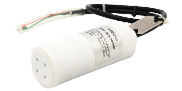
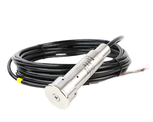
For stronger corrosive liquids, such as acidic or alkaline chemical tanks, fluoropolymer materials such as PVDF or PTFE provide much better resistance. The GLT570 Anti-Corrosion Submersible Level Sensor uses a PTFE/PVDF housing design to handle aggressive media where metal sensors may corrode over time.
GLT570 — PTFE / PVDF housing, for aggressive and corrosive media.
Selecting the wrong material does not always cause immediate failure. Corrosion can develop slowly, leading to seal degradation, diaphragm damage, or sudden leakage after weeks or months of operation.
Mistake 7: Ignoring Liquid Compatibility with Seals and Diaphragms
Even if the sensor housing is compatible with the liquid, the seals, O-rings, and diaphragm materials must also be checked. Some liquids attack certain elastomers over time, especially at elevated temperatures.
Before installation, confirm:
The liquid type and concentration
Operating temperature range
Presence of oils, solvents, acids, or alkalis
Whether the liquid contains abrasive particles
Whether the liquid may crystallize or polymerize
If the liquid is aggressive, a full-material compatibility check is essential. A sensor that looks suitable on paper may still fail if the sealing materials are not matched to the process fluid.
Mistake 8: Wiring Without Proper Grounding or Surge Protection
Submersible level sensors are often installed in pumps stations, outdoor tanks, wastewater plants, and industrial facilities where electrical noise and voltage spikes are common. Poor wiring can cause unstable signals, communication errors, or permanent damage to the transmitter.
Key wiring practices include:
Using shielded cable for analog or digital signals
Connecting the shield at one end to avoid ground loops
Ensuring a reliable ground connection
Keeping signal cables away from high-power motors and VFDs
Using surge protectors in lightning-prone areas
Verifying supply voltage before powering the sensor
For 4–20 mA sensors, check loop resistance and power supply limits. For RS485 sensors, confirm correct A/B wiring, termination, and address settings. Many “faulty sensor” problems are actually wiring or grounding issues.
Image 6 — suggested: wiring — shield grounded at one end, SPD at the enclosure, signal away from VFDs.
Mistake 9: Skipping Calibration and Range Verification
A submersible level sensor must be matched to the actual measurement range. If the range is set incorrectly, the output may appear stable but still be inaccurate.
Before final commissioning:
Confirm the tank height and usable measurement range
Check the sensor’s pressure range
Verify the output signal type, such as 4–20 mA or RS485
Test the reading at known liquid levels
Adjust zero and span if the transmitter allows configuration
Record baseline readings for future maintenance
It is also important to remember that hydrostatic pressure depends on liquid density. If the liquid density changes significantly, the level reading may shift even if the sensor is working correctly.
Mistake 10: Failing to Plan for Maintenance and Inspection
Submersible sensors are often installed and then forgotten. However, periodic inspection can prevent unexpected failures.
A simple maintenance routine should include:
Checking the cable for cuts, abrasion, or UV damage
Inspecting the cable gland and junction box for moisture
Cleaning the sensor body if fouling or scaling is visible
Verifying the reading against a known reference level
Checking for corrosion on metal fittings or suspension hardware
Ensuring the vent tube remains open at the termination end
Maintenance does not need to be complex. The main goal is to catch small problems before they become sensor failures.
Quick Installation Checklist
Ten checkpoints to clear before the loop is powered up.
Checkpoint
What to Verify
Vent tube
Cable is not kinked; vent path is open
Mounting position
Sensor is above tank bottom and away from turbulence
Mechanical support
Weight is carried by cable support, not the cable itself
Sealing
Cable gland, junction box, and entry points are properly sealed
Material selection
Housing and seals match the liquid and temperature
Wiring
Shielding, grounding, and power supply are correct
Range
Sensor range matches tank height and liquid density
Commissioning
Reading is verified at known liquid levels
Environment
Cable and electronics are protected from water and sunlight
Maintenance
Inspection schedule is defined and documented
How to Choose the Right Submersible Level Sensor for Your Application
Installation quality matters, but sensor selection matters just as much. The best installation cannot fully compensate for a sensor that is mismatched to the liquid, range, or environment.
For clean water, rainwater tanks, boreholes, sumps, and general water storage, a robust 316L stainless-steel sensor is often the right starting point. The GLT500 Water Tank Level Sensor offers an IP68-rated 316L housing and supports common industrial outputs, making it a practical option for water-level monitoring where corrosion is not the primary concern.
For chemical tanks, wastewater with aggressive constituents, or applications involving acids, alkalis, or saline liquids, a corrosion-resistant design is more suitable. The GLT570 Anti-Corrosion Submersible Level Sensor uses PTFE/PVDF materials to improve chemical resistance and reliability in harsher liquid environments.
Choosing between them depends on three questions:
What is the liquid? Water, wastewater, chemical, seawater, or mixed media?
What is the environment? Indoor tank, outdoor sump, chemical plant, or wastewater station?
What signal is required? 4–20 mA, RS485, or integration with a PLC/SCADA system?
Answering these questions early helps avoid both installation problems and premature sensor replacement.
FAQ: Submersible Level Sensor Installation
Why does my submersible level sensor drift over time?
Drifting is often caused by a blocked vent tube, sediment buildup on the diaphragm, temperature changes, or incorrect range settings. Check the vent path first, then verify the mounting position and calibration.
Can I install a submersible sensor in a tank with sludge?
Yes, but the sensor should not rest on the tank bottom. Use a bracket, cage, or stilling well to keep it above settled solids. Regular inspection is also recommended.
Is IP68 enough for outdoor installation?
IP68 protects the sensor body against continuous immersion, but it does not protect the cable gland, junction box, or wiring connections. Those points must also be sealed and protected from rain, condensation, and UV exposure.
Why does the reading fluctuate when the pump is running?
Fluctuations are usually caused by turbulence, flow noise, or pressure changes near the sensor. Move the sensor to a calmer area or install it inside a stilling well.
Can submersible level sensors measure any liquid?
No. The sensor materials must be compatible with the liquid. Clean water, mild wastewater, and many neutral liquids are less demanding, while strong acids, alkalis, solvents, and seawater may require corrosion-resistant materials.
How often should submersible level sensors be inspected?
For clean water applications, inspection every 6–12 months may be sufficient. For wastewater, chemical tanks, or outdoor installations, check every 3–6 months or according to site maintenance requirements.
Final Thoughts
Most submersible level sensor failures are not random. They follow a pattern: blocked vents, poor cable support, incorrect mounting, weak sealing, wrong material selection, bad wiring, and missing maintenance.
Avoiding these 10 common installation mistakes can dramatically improve measurement stability and service life. Pair good installation practice with the right sensor for the liquid and environment, and the system will perform far more reliably.
For general water-level monitoring, the GLT500 Water Tank Level Sensor provides a durable 316L stainless-steel solution. For corrosive or chemically aggressive liquids, the GLT570 Anti-Corrosion Submersible Level Sensor offers stronger material resistance through its PTFE/PVDF construction.
Good installation protects the sensor. The right sensor protects the process.