
- Dedicating for every
possibilities of sensing solution
- Product
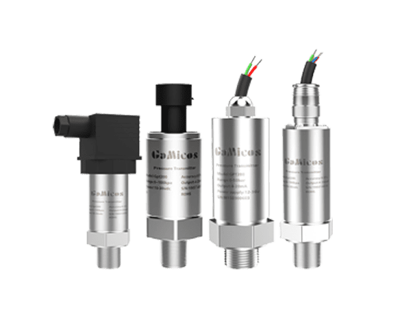
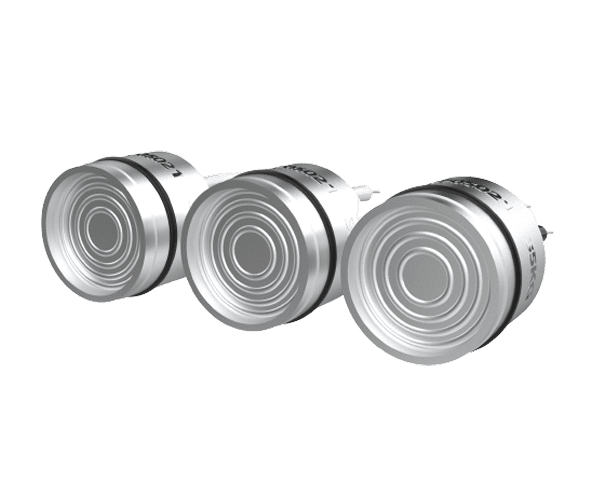
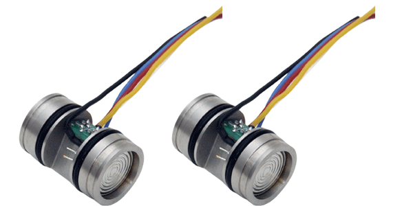
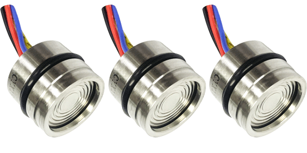
- Pressure Sensor
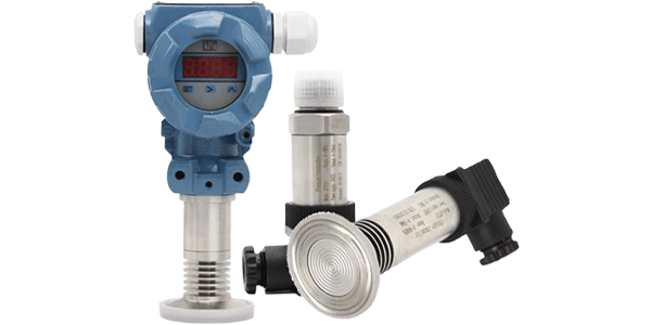
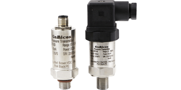
- Pressure Transmitter
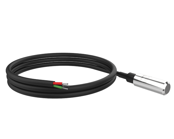
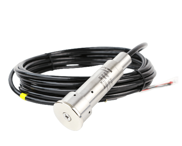
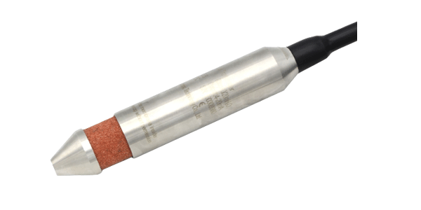
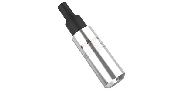
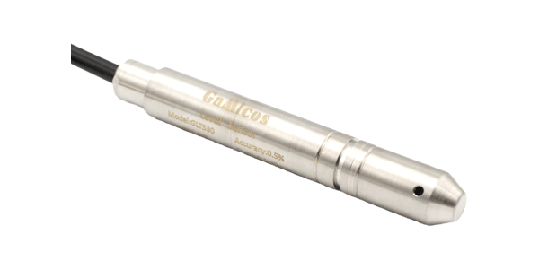
- Level Transmitter
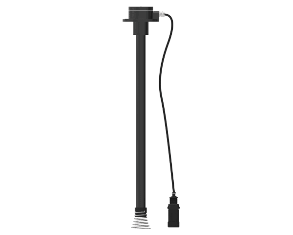
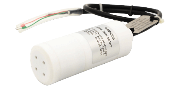
- Fuel Level Sensor
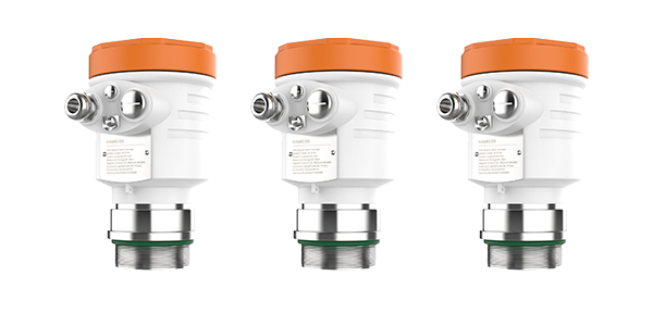
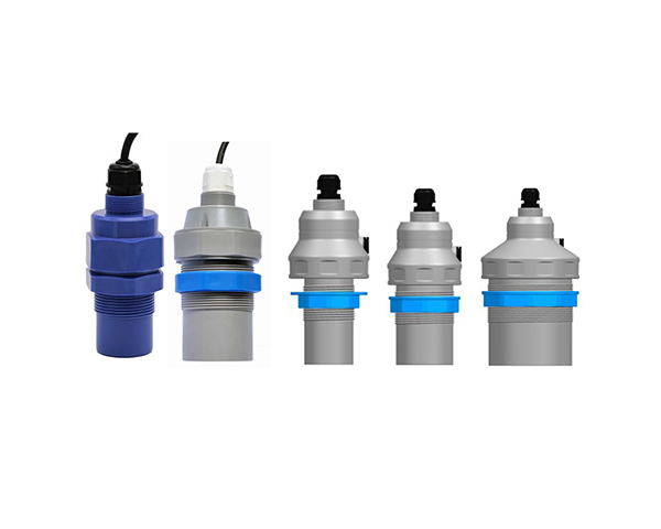
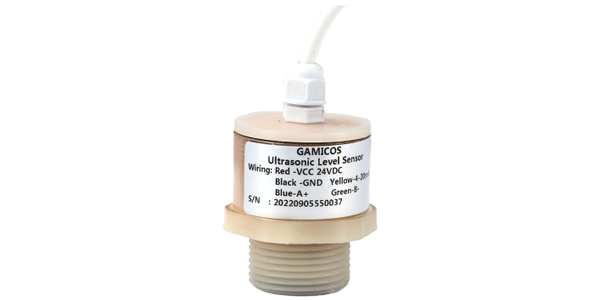
- Ultrasonic Level Sensor
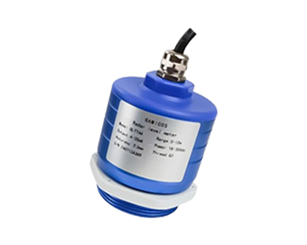
- Radar Level Sensor
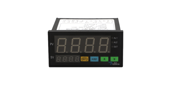
- Water Level Meter
- Accessories
- General pressure sensor Sanitary pressure sensor Differential pressure sensor I2C pressure sensor
-
General pressure sensor

Sanitary pressure sensor
Differential pressure sensor
I2C pressure sensor
- General pressure transmitter Sanitary pressure transmitter High temperature pressure transmitter Anti-corrosive pressure transmitter Industrial pressure transmitter Differential pressure transmitter Digital pressure transmitter Melt pressure transducer Sputtered Thin Film Pressure Transmitter Wireless Pressure Transmitter
-
General pressure transmitter
Sanitary pressure transmitter
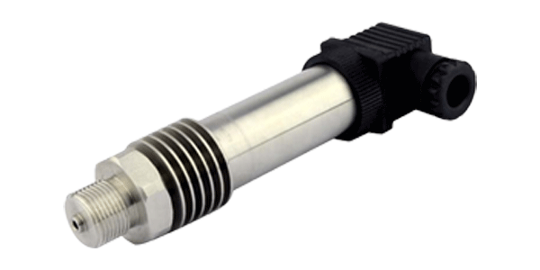
High temperature pressure transmitter
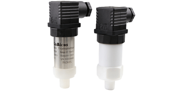
Anti-corrosive pressure transmitter
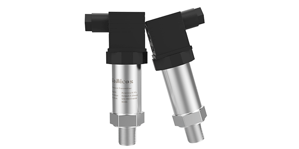
Industrial pressure transmitter
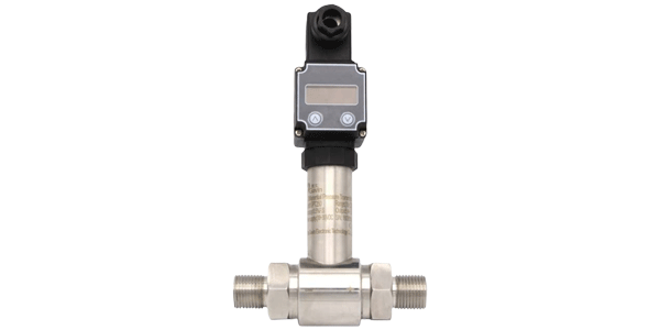
Differential pressure transmitter
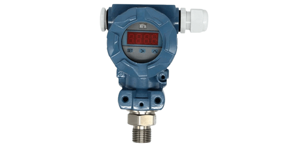
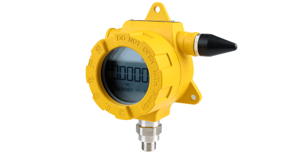
Digital pressure transmitter
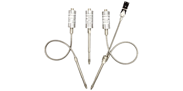
Melt pressure transducer
Sputtered Thin Film Pressure Transmitter
Wireless Pressure Transmitter
- Submersible level transmitter Anti-corrosive level transmitter Anti-pollution level transmitter Integrated temperature level transmitter Small diameter level transmitter Wireless Level Transmitter
-
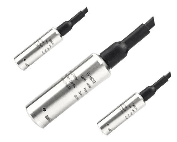
Submersible level transmitter
Anti-corrosive level transmitter
Anti-pollution level transmitter
Integrated temperature level transmitter
Small diameter level transmitter
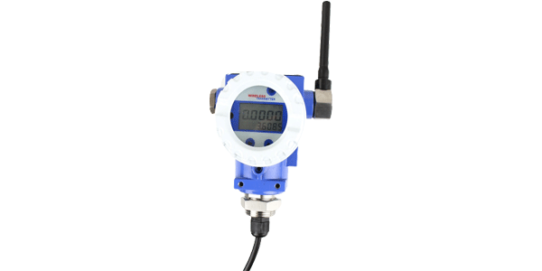
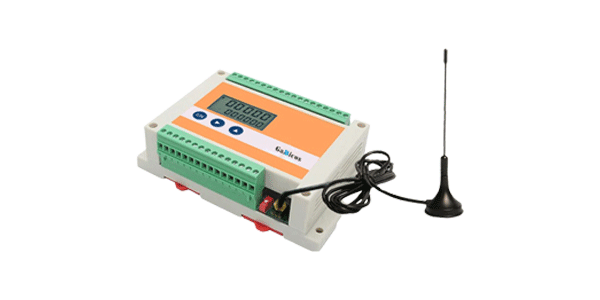
Wireless Level Transmitter
- Capacitive fuel level sensor Mechanical fuel level gauge Reed switch fuel level sensor Magnetostrictive fuel level sensor
-
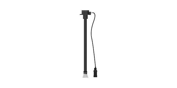
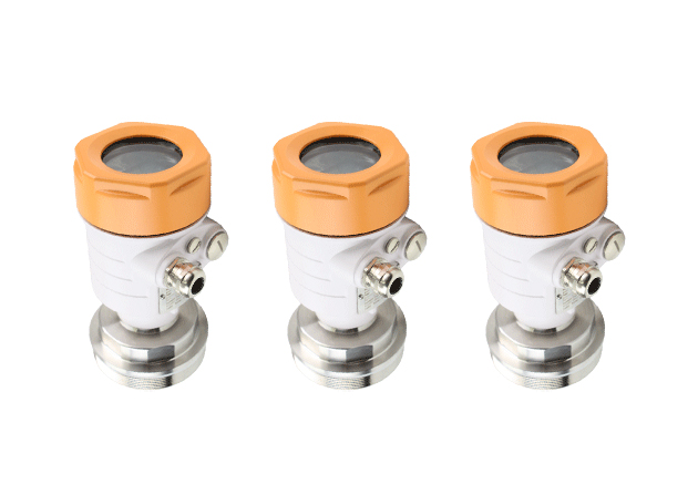
Capacitive fuel level sensor
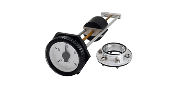
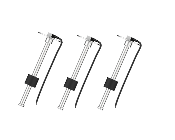
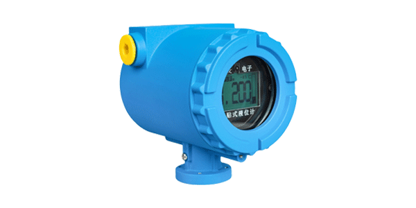
Mechanical fuel level gauge
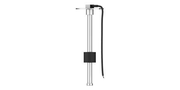
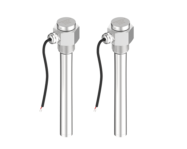
Reed switch fuel level sensor
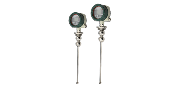
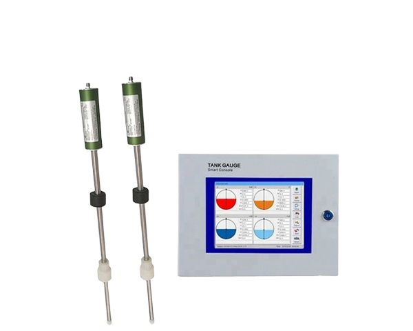
Magnetostrictive fuel level sensor
- General ultrasonic level sensor Anti-corrosive ultrasonic level sensor Industrial ultrasonic level sensor Handheld ultrasonic level sensor External ultrasonic level sensor
-
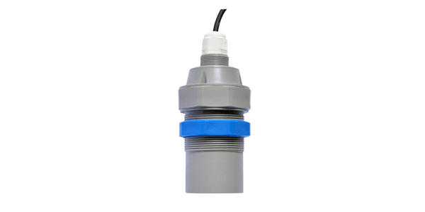
General ultrasonic level sensor
Anti-corrosive ultrasonic level sensor
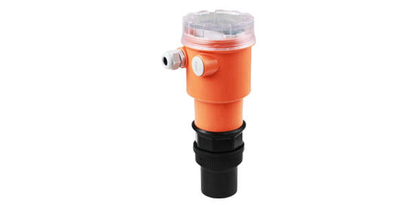
Industrial ultrasonic level sensor
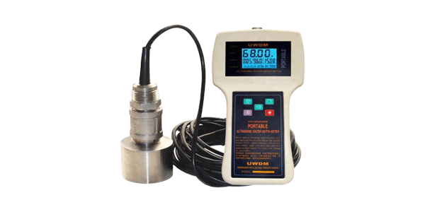
Handheld ultrasonic level sensor
External ultrasonic level sensor
- Solution
- Chemical Vehicles Oil and Gas Food and Medicine Fuel Monitoring Water treatment Machinery Manufaturing Municipal fire Hydrologic monitoring Refrigeration Drilling Exploration
-
Chemical

Vehicles
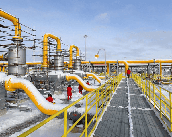
Oil and Gas
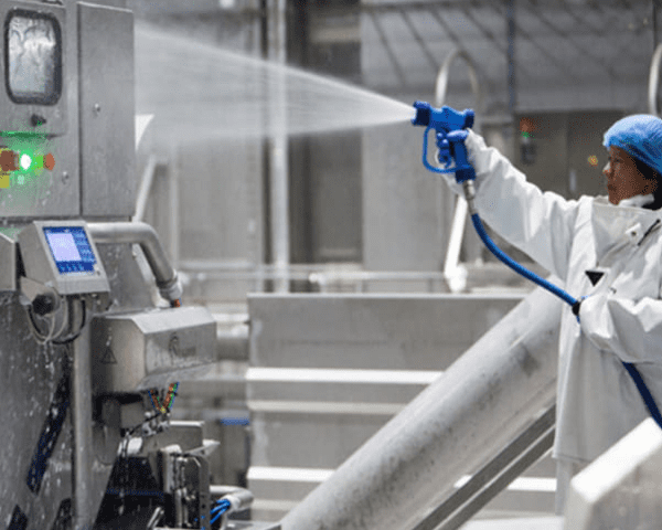
Food and Medicine
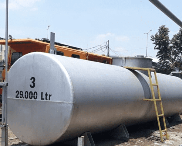
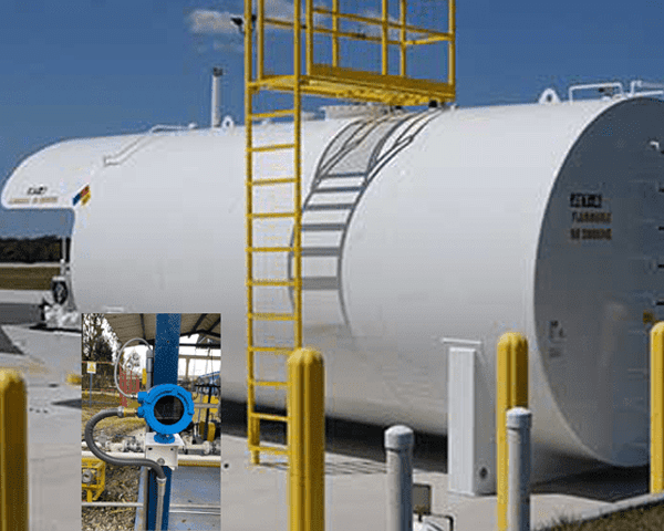
Fuel Monitoring
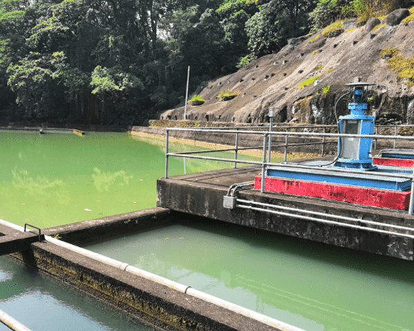
Water treatment
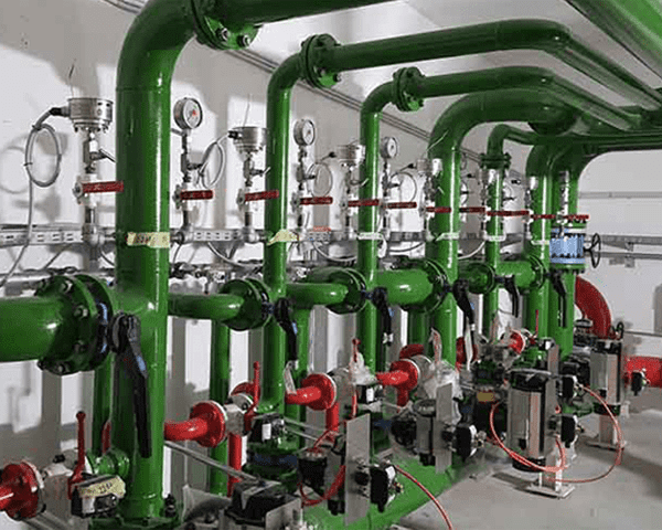
Machinery Manufaturing
Municipal fire
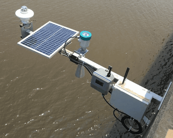
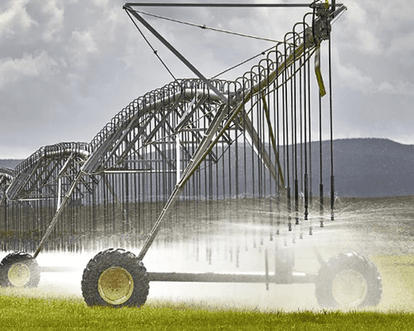
Hydrologic monitoring
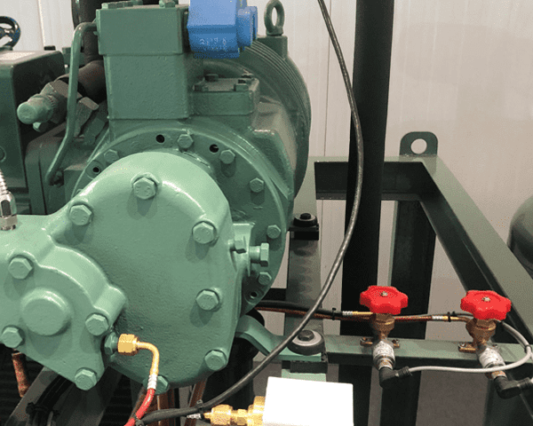
Refrigeration
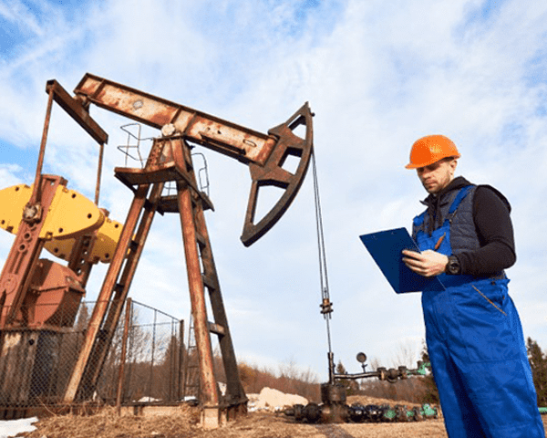
Drilling Exploration
- Service
- Support
- Blog
- IOT
- About us