Application Case · Pharmaceutical Cleanrooms
Cleanroom differential pressure is a very small value that carries a direct compliance consequence.
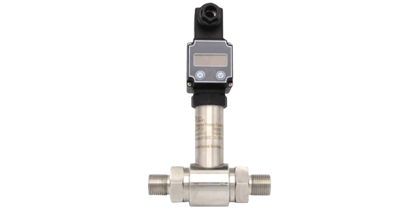
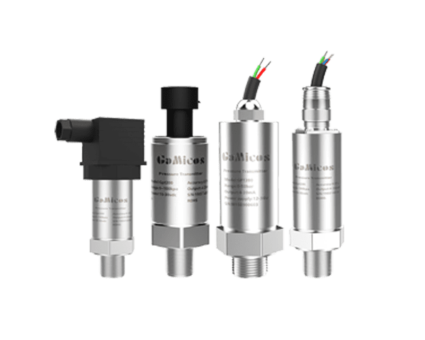
The GPT251 micro differential pressure transmitter converts the pressure difference between a room and its
reference area into a continuous signal across a ±100 Pa to 100 kPa range, so the gradient can be read
at the machine and reviewed in the BMS at the same time.
1. Industry Background
Cleanroom differential pressure is a small value that carries a large safety consequence. Pharmaceutical cleanrooms establish pressure differential gradients between rooms through supply, return and exhaust
air systems, so that air flows in a predetermined direction and the risk of contaminants entering critical production
areas from lower-grade areas, corridors or airlocks is reduced. Although the differential pressure value is very small,
it is directly related to airflow organization, the stability of the clean environment and deviation investigation.
In actual operation, door opening and closing, changes in filter resistance, damper positions and the status of exhaust
equipment all cause fluctuations in room differential pressure. If only manual inspection or mechanical differential
pressure gauges are relied upon, short-term reverse differential pressure and continuous drift are difficult to record,
and the cleanroom status is also difficult to integrate into the building automation system for unified management.
Four problems recur when a cleanroom pressure gradient is monitored with general-purpose instrumentation. They concern resolution at low differential pressure, transient events caused by door traffic, the effort of reading
scattered measuring points, and the sensitivity of micro differential pressure measurement to installation practice.
Pain point 1: Small differential pressure values exceed the resolution of ordinary pressure instruments
The pressure difference between cleanroom rooms is usually far lower than conventional pipeline pressure.
If the range is too large, small changes are submerged in full-scale error and zero drift, so the control system
cannot promptly identify a decrease or a reversal of the differential pressure.
Pain point 2: Door opening and air volume disturbance cause transient fluctuations
The passage of personnel and materials changes the boundary conditions of the room, and an imbalance between supply
and return air also causes rapid differential pressure changes. With only local pointer readings, short-term
abnormalities leave no trace, and deviation investigations lack a trend basis.
Pain point 3: Scattered measuring points in multiple rooms make manual recording inefficient
Production areas, airlocks and corridors may form a multi-stage pressure gradient. Reading gauges point by point is
not only labor-intensive but also involves non-synchronized reading times and recording errors, which makes unified
monitoring difficult.
Pain point 4: Installation orientation and pressure lines affect the zero point
Micro differential pressure measurement is more sensitive to installation attitude and pressure piping. If the
installation orientation of the transmitter differs from the commissioning orientation, or if the piping is bent or
leaks, a zero offset is introduced and false alarms are caused.
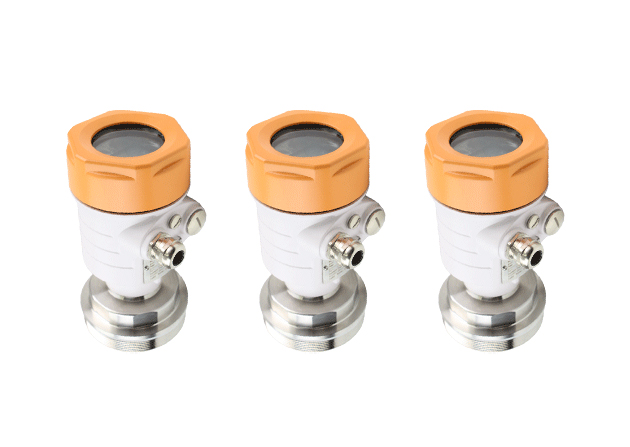
3. Product Recommendation: GPT251 Micro Differential Pressure Transmitter
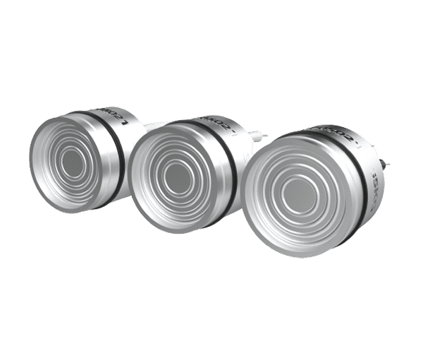
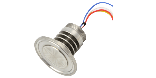
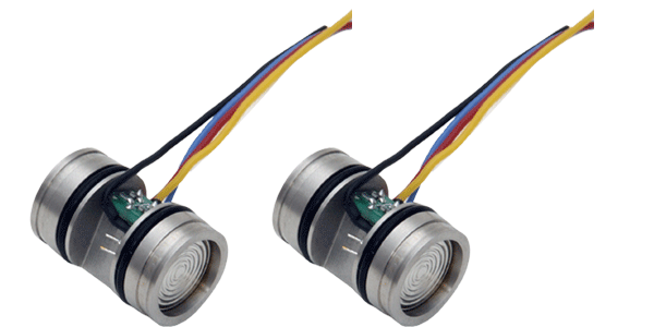
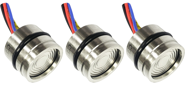
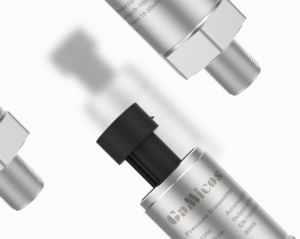
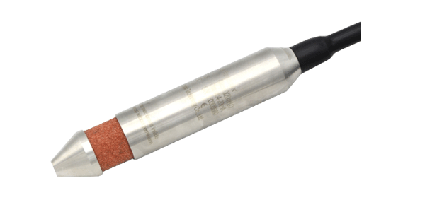
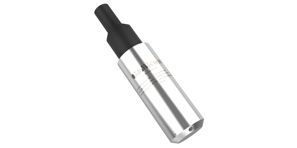
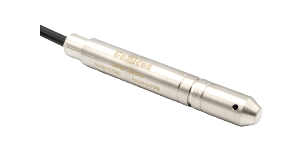
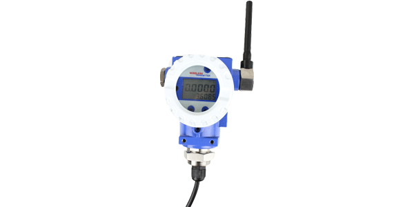
The GPT251 is built for the low end of the differential pressure scale where general transmitters lose resolution. It is an industrial transmitter designed for micro differential pressure measurement, with a measuring range covering
±100 Pa to 100 kPa. Models below 5 kPa use an elastic silicone gel to protect the chip and are suitable for gas
differential pressure measurement where the gas is not corrosive to silicon or silicone gel; models of 5 kPa and above
use a 316L stainless steel isolating diaphragm filled with silicone oil. The product is fully digitally calibrated with
no movable potentiometers, and is suitable for continuously converting the pressure difference across a cleanroom into
a signal that the control system can read.
How the product maps to each pain point
±100 Pa to 100 kPa micro differential pressure range → Pain point 1
The appropriate range can be selected for cleanroom pressure gradients, filter resistance or air pressure measuring
points, avoiding the insufficient resolution that occurs when a wide-range pressure instrument is used to measure
a small signal.
Full digital calibration and compensation → Pain points 1 and 2
Temperature compensation, linearity compensation and full digital calibration improve temperature drift and stability,
providing a more consistent output for continuous trend monitoring.
Multiple standard outputs → Pain point 3
Supports 4–20 mA, 0–10 mA, 0–20 mA, 1–5 V, 0–5 V, 0–10 V, 0.5–4.5 V, RS485 and I2C, making it easy to connect to a
PLC, BMS or environmental monitoring system.
Surge and reverse polarity protection → Field reliability
Reduces the effect of on-site wiring or power fluctuations on the transmitter circuit and decreases non-measurement
faults during commissioning.
Dual pressure port structure → Pressure gradient management
The high- and low-pressure ports are connected to the cleanroom and the reference area respectively, directly
outputting the pressure difference between the two areas and supporting centralized management of the pressure gradient.
Installation orientation and pressure line practice → Pain point 4
Install in the commissioning orientation to keep the zero point consistent, route the pressure lines at equal length
and verify airtightness before acceptance.
4. Key Selection Information
Range, wetted material and output are the three decisions that determine whether the transmitter suits the measuring point. The table below lists the configuration options that must be confirmed before ordering.
Table 1. GPT251 key selection parameters
|
Item
|
Configuration / Description
|
|
Measuring range
|
±100 Pa to 100 kPa
|
|
Pressure type
|
Differential pressure
|
|
Typical supply
|
24 VDC / 12 VDC / 5 VDC / 3.3 VDC, optional
|
|
Output
|
4–20 mA, 0–10 mA, 0–20 mA, 1–5 V, 0–5 V, 0–10 V, 0.5–4.5 V, RS485, I2C
|
|
Wetted parts for <5 kPa
|
Elastic silicone gel protection; suitable for gases not corrosive to silicon and silicone gel
|
|
Wetted parts for ≥5 kPa
|
316L isolating diaphragm, silicone oil filled
|
|
Installation notes
|
Install in the commissioning orientation; avoid mechanical vibration and strong electromagnetic interference
|
5. Customer Application Case: Digitizing the Pressure Gradient Between Production Rooms, Airlocks and Corridors
5.1 Project background
The upgrade goal was to turn point-by-point gauge readings into a continuous record of the cleanroom pressure gradient. A pharmaceutical manufacturing facility needed to digitally upgrade the pressure gradient between its core production
rooms, airlocks and corridors. The original system relied mainly on mechanical differential pressure gauges and manual
records and could not continuously record the differential pressure changes caused by door opening processes and air
volume fluctuations.
The following is a desensitized typical project scenario built on the capabilities of the product and does not refer to any specific customer.
5.2 Solution
The solution measures the difference between each room and its reference area at a fixed point, then routes every signal into one system. Each element of the configuration was fixed during commissioning as follows.
Table 2. Configuration decisions in the cleanroom pressure gradient upgrade
|
Item
|
Configuration
|
|
Installation location
|
The transmitter is installed horizontally in the equipment interstice or technical corridor outside the clean area;
the high-pressure port is connected to the room with the higher cleanliness class, and the low-pressure port to the
airlock or corridor; the pressure lines are routed at equal length and checked for airtightness.
|
|
Product selection
|
GPT251 micro differential pressure transmitter; an appropriate Pa-level range is selected according to the design
differential pressure and the permissible fluctuation range, with a 24 VDC supply and 4–20 mA output.
|
|
Monitoring objective
|
Continuously monitor the actual differential pressure between rooms and identify abnormal conditions such as a
decrease or reversal of the differential pressure and doors left open for extended periods.
|
|
System integration
|
The 4–20 mA signal is connected to the PLC or BMS to form real-time values, trend curves and deviation records;
alarm thresholds are jointly determined by the cleanroom design documents, the process risk assessment and the
on-site confirmation results, and generic values are not used to replace project-specific settings.
|
|
Commissioning and acceptance
|
After installation, carry out a zero point check, confirmation of the positive and negative pressure direction,
a leakage check of the pressure lines and a door opening and closing disturbance test, and compare the transmitter
readings with the calibrator results.
|
5.3 Application results and acceptance value
After installation, every room in the gradient becomes a continuously recorded data point instead of a periodic gauge reading. The following effects were observed in the upgrade, grouped by the benefit they produced.
Continuous differential pressure visibility
Manual inspection time points are extended into a continuous signal, making it possible to record the effects of
door opening, filter resistance changes and air volume disturbances on the pressure gradient.
Centralized management of multiple rooms
Scattered measuring points are connected to the PLC or BMS through standard outputs, so that room status, trends and
alarms can be viewed in a unified way.
Traceable evidence of abnormalities
Historical curves provide a time basis for deviation investigations of reverse differential pressure, persistently
low values and equipment faults.
Project-specific range matching
The ±100 Pa to 100 kPa range allows the range to be selected for each measuring point, instead of using a single
wide-range instrument to cover all areas.
Table 3. Acceptance dimensions before and after the upgrade
|
Acceptance dimension
|
Before
|
After
|
|
Measurement method
|
Manual inspection or readings from independent instruments
|
A continuous measurement process aligned with the position of the product
|
|
Data acquisition
|
Dependent on ad-hoc operations or scattered records
|
Reviewable on-site and system data obtained at fixed measuring points
|
|
Maintenance management
|
Troubleshooting only after an abnormality has occurred
|
Trends, alarms and comparisons incorporated into routine mechanisms
|
6. Application Scope
The GPT251 suits measuring points where the pressure difference is small and must be monitored continuously. Typical applications share a requirement for a low-range differential measurement, a standard output signal and a wetted
material matched to the gas being measured.
Pharmaceutical cleanrooms: room-to-room pressure gradients, airlock and corridor references, and the
multi-stage gradient across a production area.
Filter and air path monitoring: filter resistance and air pressure measuring points where a low-range
differential signal indicates loading or imbalance.
Building and environmental systems: continuous pressure difference values connected to a PLC, BMS or
environmental monitoring system.
Gas differential pressure, low range: models below 5 kPa with elastic silicone gel protection, for
gases not corrosive to silicon or silicone gel.
Gas or liquid differential pressure, higher range: models of 5 kPa and above with a 316L stainless steel
isolating diaphragm filled with silicone oil.
7. Frequently Asked Questions
What differential pressure range does the GPT251 cover?
The measuring range covers ±100 Pa to 100 kPa, which allows a Pa-level range to be selected for cleanroom pressure
gradients, filter resistance or air pressure measuring points instead of using one wide-range instrument across all areas.
Which wetted materials are used at low and high ranges?
Models below 5 kPa use an elastic silicone gel to protect the chip and are suitable for gases not corrosive to silicon
or silicone gel. Models of 5 kPa and above use a 316L stainless steel isolating diaphragm filled with silicone oil.
Which output signals are available?
The GPT251 supports 4–20 mA, 0–10 mA, 0–20 mA, 1–5 V, 0–5 V, 0–10 V, 0.5–4.5 V, RS485 and I2C. Typical supply
options are 24 VDC, 12 VDC, 5 VDC and 3.3 VDC.
How should the transmitter be installed to avoid a zero offset?
Install it in the commissioning orientation, route the pressure lines at equal length and verify airtightness before
acceptance. Mechanical vibration and strong electromagnetic interference should be avoided at the mounting position.
Can the GPT251 be integrated into a BMS or PLC?
Yes. A standard output such as 4–20 mA or RS485 is connected to the PLC or BMS to form real-time values, trend curves
and deviation records. Alarm thresholds should be determined from the cleanroom design documents, the process risk
assessment and on-site confirmation results rather than generic values.
What checks are performed during commissioning and acceptance?
Carry out a zero point check, confirm the positive and negative pressure direction, perform a leakage check of the
pressure lines and a door opening and closing disturbance test, and compare the transmitter readings with the
calibrator results.
8. Specifications
The table below consolidates the technical data referenced throughout this page. Options marked as optional are determined at ordering according to the application requirements.
Table 4. GPT251 technical specifications
|
Parameter
|
Value / Option
|
|
Measuring range
|
±100 Pa to 100 kPa
|
|
Pressure type
|
Differential pressure
|
|
Supply voltage
|
24 VDC / 12 VDC / 5 VDC / 3.3 VDC, optional
|
|
Output signal
|
4–20 mA, 0–10 mA, 0–20 mA, 1–5 V, 0–5 V, 0–10 V, 0.5–4.5 V, RS485, I2C
|
|
Wetted parts, <5 kPa
|
Elastic silicone gel protection; gases not corrosive to silicon and silicone gel
|
|
Wetted parts, ≥5 kPa
|
316L isolating diaphragm, silicone oil filled
|
|
Calibration
|
Fully digital calibration, no movable potentiometers
|
|
Circuit protection
|
Surge and reverse polarity protection
|
|
Installation
|
Install in the commissioning orientation; avoid mechanical vibration and strong electromagnetic interference
|
Discuss your cleanroom differential pressure monitoring requirement
Range, wetted material, output signal and installation position need to be confirmed together before a differential
pressure transmitter is specified. Send us the design differential pressure of each room, the reference area and the
existing BMS or PLC interface, and we will confirm the configuration for your cleanroom pressure gradient.
GAMICOS — Xi'an Gavin Electronic Technology Co., Ltd.
www.gamicos.com · info@gamicos.com · +86 029-81292510