Application Case · Industrial Hydraulics
For hydraulic power units that need both on-site confirmation at the machine and continuous data at the control cabinet,
a single integrated pressure transmitter is easier to maintain than a separate mechanical gauge plus a blind transmitter.
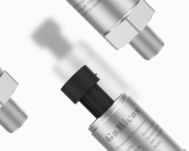
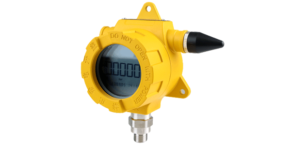
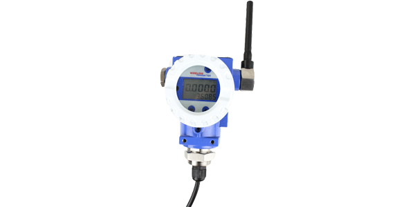
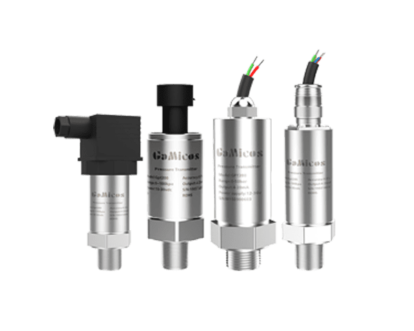
The GPT204 combines a local digital display with 4–20 mA, 0–10 V or RS485 output across a -0.1 MPa to 100 MPa range.
1. Industry Background
Hydraulic system pressure is the most direct indicator of power unit condition. Hydraulic power units provide stable power for presses, machine tools, forming equipment and automated production lines.
System pressure directly reflects pump unit load, relief valve setting, actuator resistance and piping condition,
and is a key parameter for equipment start-up commissioning, operation monitoring and troubleshooting.
Conventional mechanical pressure gauges are convenient for on-site observation but cannot feed data into a control system;
using transmitters without a display alone forces on-site maintenance personnel to rely on PLC screens or external instruments.
For hydraulic power units where quick confirmation at the machine and remote acquisition at the control cabinet are both required,
an integrated structure combining local display and signal transmission is easier to maintain.
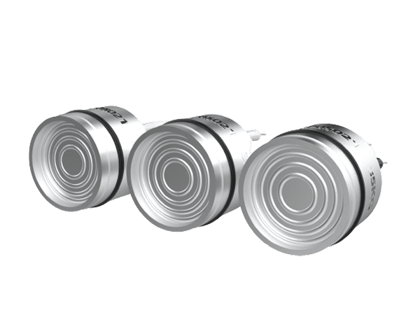
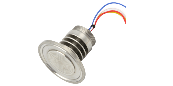
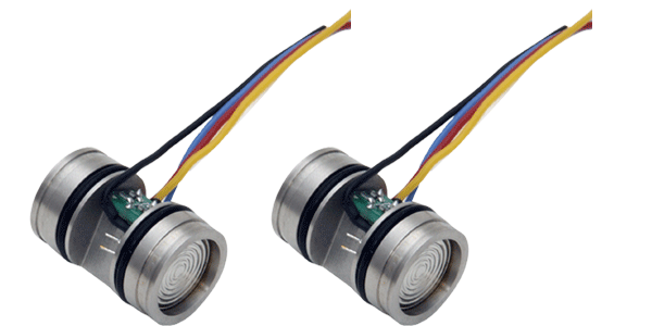
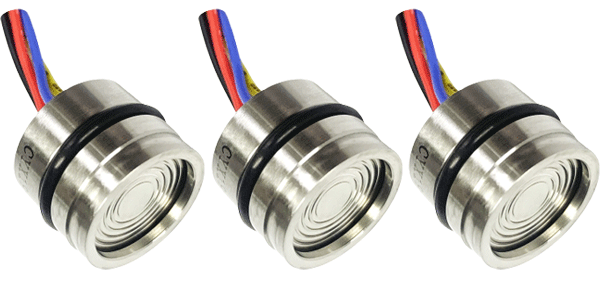
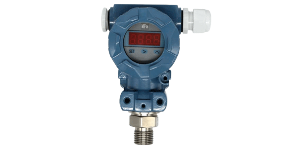
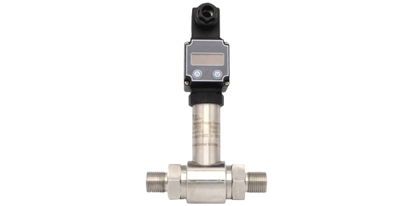
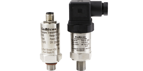
The GPT204 compact digital pressure transmitter uses a silicon piezoresistive sensor with a stainless steel isolating diaphragm
together with dedicated digital circuitry. After signal amplification and linearity compensation, it displays the measured value
locally on the head and outputs a standard signal. It is suitable for hydraulics and pneumatics, constant-pressure water supply,
petrochemical, and general measurement and control applications.
2. Industry Pain Points
Four practical problems recur when pressure monitoring is retrofitted onto existing hydraulic equipment. They concern data separation, commissioning workflow, range selection and long-term reliability in an oily, vibrating environment.
Pain point 1: On-site pressure gauges and control system data are separated
Mechanical gauges can only be read locally, so the PLC cannot obtain a continuous pressure value.
Adding a separate transmitter increases the number of measuring points, fittings and maintenance items,
and the on-site reading may still disagree with the system reading.
Pain point 2: Equipment commissioning depends on back-and-forth confirmation
When maintenance personnel adjust the pump unit or valve group, they must repeatedly verify the pressure between
the hydraulic power unit and the control cabinet, which lengthens commissioning time and can also cause misjudgement
due to communication errors.
Pain point 3: A wide pressure span makes unified selection difficult
Different hydraulic circuits may involve vacuum, low-pressure control circuits and high-pressure actuator circuits.
A mismatched range results in insufficient resolution or a risk of overload.
Pain point 4: Oil, vibration and the industrial environment test reliability
Hydraulic power units involve oil contact, pressure pulsation, temperature variation and equipment vibration.
If the wetted diaphragm, housing, protection and mounting position are not matched to the application,
the risk of drift, leakage and unplanned downtime increases.
3. Product Recommendation: GPT204 Compact Digital Pressure Transmitter
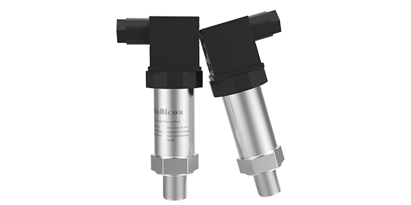
The GPT204 answers the four pain points above with one hardware configuration. It is a compact pressure transmitter that combines local digital display with remote output.
Its range covers -0.1 MPa to 100 MPa, with gauge, absolute or sealed gauge pressure available.
The product uses an integrated structure of a silicon piezoresistive sensor and a 316L stainless steel isolating diaphragm,
supports 4–20 mA, 0–10 V or RS485 output, and makes the electrical connection through a Hirschmann connector.
How the product maps to each pain point
Local display + remote output → Pain points 1 and 2
A single measuring point allows the pressure to be read at the machine and the signal to be sent to the PLC at the same time,
reducing the data inconsistency caused by installing a mechanical gauge and a transmitter separately.
Wide range from -0.1 MPa to 100 MPa → Pain point 3
Covers vacuum, low-pressure and high-pressure hydraulic circuits, and selecting the range according to the actual working
pressure reduces the risk of range mismatch.
Multiple accuracy classes → Application fit
0.5%FS, 0.25%FS and custom 0.1%FS options allow performance and cost to be balanced for general monitoring,
equipment control or testing requirements.
Multiple remote interfaces → Control architecture fit
4–20 mA, 0–10 V and RS485 outputs suit analog control systems or digital equipment management.
316L isolating diaphragm and integrated design → Pain point 4
Suitable for fluids compatible with 304, 316L or ceramic, reducing the risk of the pressure medium acting directly
on the sensing element.
≤1 ms response and IP65 protection → Field reliability
Supports acquisition of rapid pressure changes in hydraulic systems and meets the dust- and water-protection
requirements of general industrial sites.
4. Key Selection Information
Range, pressure type and output are the three decisions that determine whether the instrument fits the circuit. The table below lists the configuration options that must be confirmed before ordering.
Table 1. GPT204 key selection parameters
|
Item
|
Configuration / Description
|
|
Range
|
-0.1 MPa…0 kPa to 10 kPa…100 MPa
|
|
Pressure type
|
Gauge G / Absolute A / Sealed gauge S
|
|
Output
|
4–20 mA / 0–10 V (three-wire) / RS485 (four-wire)
|
|
Accuracy class
|
0.5%FS / 0.25%FS / 0.1%FS (custom)
|
|
Supply voltage
|
15–30 VDC, nominal 24 VDC
|
|
Operating temperature
|
-40 to +85 °C
|
|
Response time
|
≤1 ms
|
|
Measured medium
|
Fluids compatible with 304, 316L or ceramic
|
|
Diaphragm material
|
316L, titanium alloy or ceramic, optional
|
|
Electrical connection
|
Hirschmann connector
|
|
Protection class
|
IP65
|
5. Customer Application Case: Unified Pressure Monitoring on Hydraulic Power Units
5.1 Project background
The retrofit goal was to give the controller access to pressure trends without losing the ability to confirm pressure at the machine. A metalworking equipment manufacturer needed to add unified pressure monitoring to its hydraulic power units.
The original equipment used mechanical pressure gauges, which on-site personnel could read, but the controller could not
store pressure trends; after transmitters without a display were added, there was again no intuitive means of confirmation
at the machine.
The following is a desensitized typical project scenario built on the capabilities of the product and does not refer to any specific customer.
5.2 Solution
The solution keeps one measuring point and splits the signal into a local readout and a PLC input. Each element of the configuration was fixed during commissioning as follows.
|
Item
|
Configuration
|
|
Installation location
|
Install the GPT204 at a stable measuring point on the hydraulic pump outlet or the main pressure line, and use suitable
isolation valves or damping measures to reduce the effects of maintenance work and pressure pulsation.
|
|
Product selection
|
GPT204; the range is determined according to the maximum working pressure of the system and the permissible overload,
gauge pressure is selected as the pressure type, the accuracy class is selected as 0.25%FS or another class according to
the control requirements, and a 24 VDC supply is used.
|
|
Signal scheme
|
Select 4–20 mA when analog control is required; RS485 can be selected when digital networking is required.
The local display head is used for commissioning and inspection, and the remote signal is connected to the PLC.
|
|
Monitoring objective
|
Display and record the pump outlet pressure and identify insufficient pressure, abnormal pressure rise, relief valve
setting deviation and actuator load changes.
|
|
Commissioning and acceptance
|
Verify the sensor range, pressure port and sealing material; compare the local display and the PLC reading with a
reference pressure source at several pressure points, and verify the broken-wire or over-limit alarm logic.
|
5.3 Application results
After installation, pressure information is available at the machine and in the control system at the same time. The following effects were observed in the retrofit, grouped by the design feature that produced them.
Integrated dual channel
One measuring point provides both local display and a remote signal, reducing the parallel installation of a mechanical
pressure gauge and a separate transmitter.
≤1 ms response
Rapid pressure changes in the hydraulic circuit can be tracked, providing more timely data for equipment commissioning
and fault analysis.
Three output options
4–20 mA, 0–10 V and RS485 can be adapted to different PLC and equipment control architectures.
Multi-level accuracy configuration
0.5%FS, 0.25%FS and custom 0.1%FS make it easier to select the right class for monitoring, control or testing purposes.
Cross-check between field and system
Maintenance personnel can directly compare the display head and the PLC reading, shortening the troubleshooting path
for signal-chain faults.
6. Application Scope
The GPT204 suits pressure measurement points where local reading and signal transmission are both needed. Typical applications share a requirement for a standard output signal, a compact housing and a wetted material compatible
with the medium.
Hydraulics and pneumatics: pump outlet pressure, valve group pressure, actuator circuit pressure and test benches.
Constant-pressure water supply: pressure monitoring and control where a local readout supports maintenance checks.
Petrochemical: pressure measurement points on fluids compatible with 304, 316L or ceramic.
General measurement and control: equipment where a standard analog or RS485 signal must reach a controller.
7. Frequently Asked Questions
Can the GPT204 replace both a mechanical gauge and a separate transmitter?
Yes, for a measuring point that needs both a local reading and a signal to the controller. The GPT204 displays the
measured value on its head and outputs 4–20 mA, 0–10 V or RS485 at the same time, so one measuring point serves both purposes.
What pressure range does the GPT204 cover?
The range covers -0.1 MPa to 100 MPa, available as gauge, absolute or sealed gauge pressure. This spans vacuum,
low-pressure control circuits and high-pressure actuator circuits.
Which output signal should be selected for a hydraulic power unit?
Select 4–20 mA when the PLC uses analog control, and RS485 when digital networking or equipment management is required.
A 0–10 V output is also available in three-wire configuration. The supply voltage is 15–30 VDC, nominal 24 VDC.
Is the GPT204 suitable for oil contact in hydraulic systems?
It uses a 316L stainless steel isolating diaphragm with optional titanium alloy or ceramic, and is intended for fluids
compatible with 304, 316L or ceramic. Compatibility with the specific hydraulic oil should be confirmed before ordering.
How is the transmitter verified during commissioning?
Verify the sensor range, pressure port and sealing material first, then compare the local display and the PLC reading
against a reference pressure source at several pressure points, and check the broken-wire or over-limit alarm logic.
What response time and protection class does it provide?
The response time is ≤1 ms, which supports acquisition of rapid pressure changes in hydraulic circuits.
The protection class is IP65, meeting the dust- and water-protection requirements of general industrial sites.
8. Specifications
The table below consolidates the technical data referenced throughout this page. Options marked as custom are determined at ordering according to the application requirements.
Table 3. GPT204 technical specifications
|
Parameter
|
Value / Option
|
|
Measurement range
|
-0.1 MPa…0 kPa to 10 kPa…100 MPa
|
|
Pressure type
|
Gauge G / Absolute A / Sealed gauge S
|
|
Output signal
|
4–20 mA / 0–10 V (three-wire) / RS485 (four-wire)
|
|
Accuracy class
|
0.5%FS / 0.25%FS / 0.1%FS (custom)
|
|
Supply voltage
|
15–30 VDC, nominal 24 VDC
|
|
Operating temperature
|
-40 to +85 °C
|
|
Response time
|
≤1 ms
|
|
Measured medium
|
Fluids compatible with 304, 316L or ceramic
|
|
Diaphragm material
|
316L, titanium alloy or ceramic, optional
|
|
Electrical connection
|
Hirschmann connector
|
|
Protection class
|
IP65
|
Discuss your hydraulic pressure monitoring requirement
Range, pressure type, output signal and wetted material need to be confirmed together before an instrument is specified.
Send us the working pressure range, the medium and the existing controller interface, and we will confirm the configuration
for your hydraulic power unit.
GAMICOS — Xi'an Gavin Electronic Technology Co., Ltd.
www.gamicos.com · info@gamicos.com · +86 029-81292510