I. Industry Background
HVAC (Heating, Ventilation, and Air Conditioning) systems represent the single largest source of energy consumption in modern commercial buildings. According to the International Building Energy Efficiency Committee, HVAC accounts for 40–60% of total energy use in commercial buildings. In data center environments, cooling system energy consumption is a direct determinant of PUE (Power Usage Effectiveness)—one of the most critical operational metrics in the industry.
At the same time, global building energy regulations are becoming increasingly stringent. The EU's Energy Performance of Buildings Directive (EPBD) mandates that all new buildings must meet "nearly zero-energy" standards by 2030. In China, the Standard for Energy Efficiency of Public Buildings, along with the U.S. ASHRAE 90.1 series, continues to raise mandatory efficiency requirements with each revision. In the post-COVID era, indoor air quality (IAQ) and temperature control stability have also become substantive considerations for tenants when selecting sites.
Within any HVAC system, the pressure of the chilled water and cooling water networks is a fundamental parameter that underpins overall system operation. The discharge pressure of the circulation pumps determines whether chilled water can be delivered to the highest terminal units in the building; the supply-return differential pressure reflects the overall resistance characteristics and hydraulic balance of the network; and the pressure at branch terminals directly affects whether those zones receive their design flow rates. Continuous, accurate pressure data collection is the prerequisite for variable-frequency energy-saving control, early fault diagnosis, and hydraulic balance regulation in HVAC systems.
II. Industry Pain Points
-
1. Hydraulic Imbalance Leading to Frequent Temperature Complaints
Large building HVAC pipe networks often span dozens of floors and hundreds of terminal zones. Due to differences in pipeline lengths, localized resistance variations, and structural changes from past retrofits, hydraulic resistance differs significantly across branches. Over-supply to near-end zones and under-supply to far-end zones are common, manifesting as temperature discrepancies between upper and lower floors and inconsistent comfort between sun-facing and shaded areas—leading to frequent tenant complaints. Without pressure data at critical nodes, facility teams must rely on trial-and-error valve adjustments, a lengthy process that rarely achieves a stable balance.
-
2. Constant-Speed Pump Operation Wastes Significant Energy
Without reliable pressure feedback, most buildings operate circulation pumps at fixed full speed to ensure that even the most disadvantaged loop receives adequate head pressure. This means that during partial-load periods—nights, weekends, and shoulder seasons—the system continues to consume full transport energy while terminal valves throttle excess pressure. That throttled energy is essentially "eaten" by the valves and converted entirely into wasted heat. Industry estimates suggest this type of waste can account for 25–40% of total pump energy consumption.
-
3. Pipe Blockages and Valve Faults Are Difficult to Pinpoint
Issues such as scale buildup, filter clogging, valve sticking, or actuator failure in HVAC pipe networks often do not trigger obvious system-wide anomalies in their early stages—only presenting as gradual degradation of cooling performance in localized zones. Maintenance teams typically only begin investigating after tenants file complaints, and the troubleshooting process requires step-by-step measurements and manual inspections, often taking hours in large buildings. This low fault-localization efficiency directly prolongs the impact of system failures.
-
4. Water Hammer Frequently Damages Instruments
Rapid opening/closing of motorized valves and start/stop cycling of pumps induce water hammer effects in the piping, with instantaneous pressure spikes reaching 2–4 times normal operating pressure. Standard pressure transmitters lack sufficient overload capacity and suffer gradual sensor damage under repeated water hammer impacts—manifesting as increasing zero drift and decreasing accuracy. These units typically require replacement every 1–2 years, creating a continuous maintenance cost burden.
-
5. Instruments Operate in Isolation, Unable to Integrate with Building Intelligence Systems
A large number of existing buildings still rely on local dial-type pressure gauges in their HVAC systems, which cannot transmit data remotely or log readings. The BMS (Building Management System) has no visibility into the actual pressure status of the pipe network. Even so-called "smart buildings" remain effectively blind at the most fundamental water-system level, unable to achieve automatic optimization based on real-time operating conditions.
III. Product Recommendation: GPT200 Diffused Silicon Pressure Transmitter
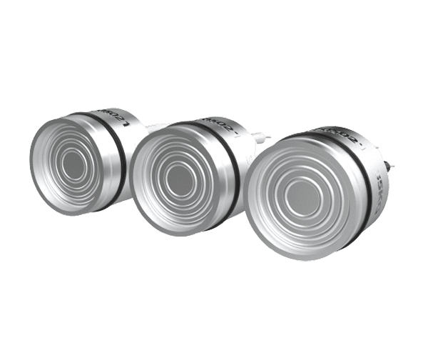
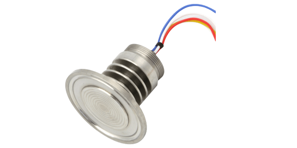
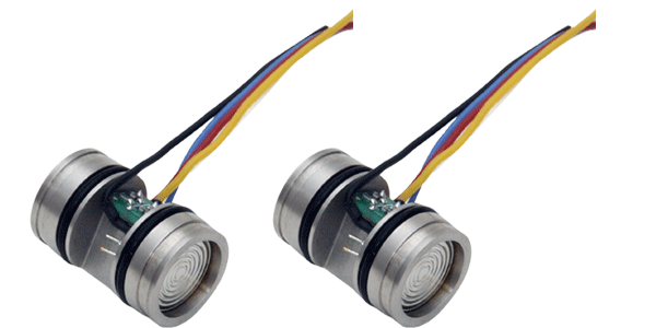
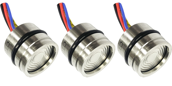
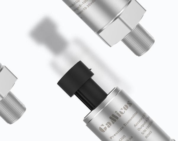
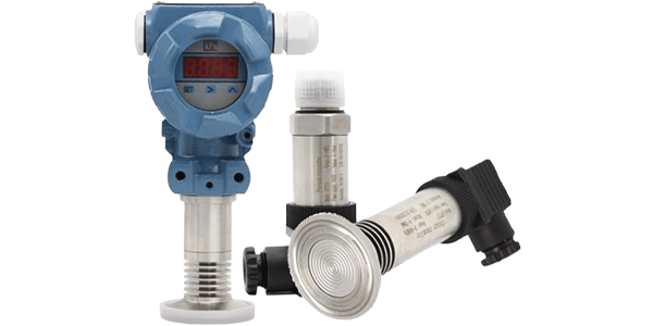
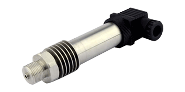
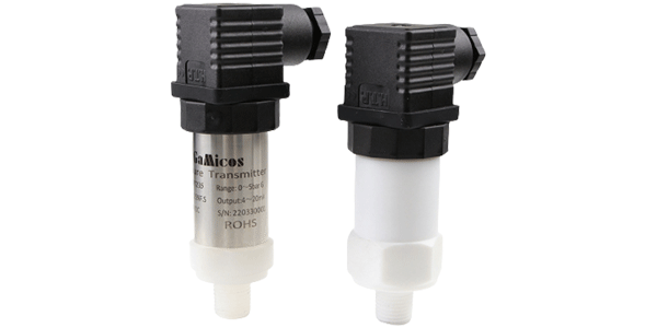
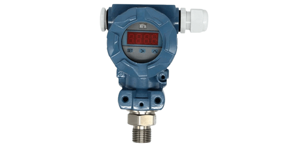
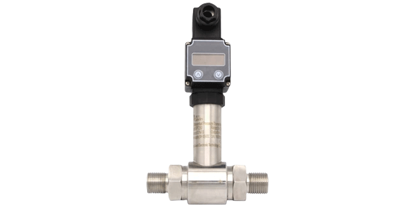
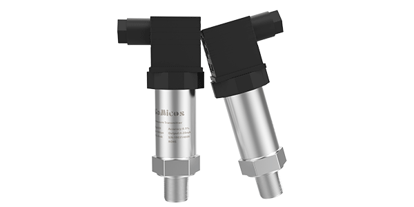
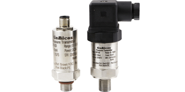
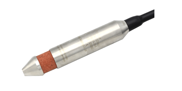
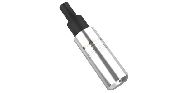
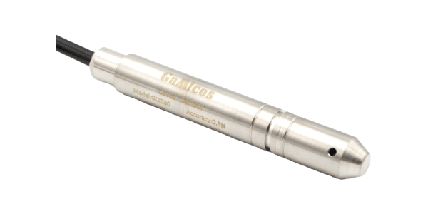
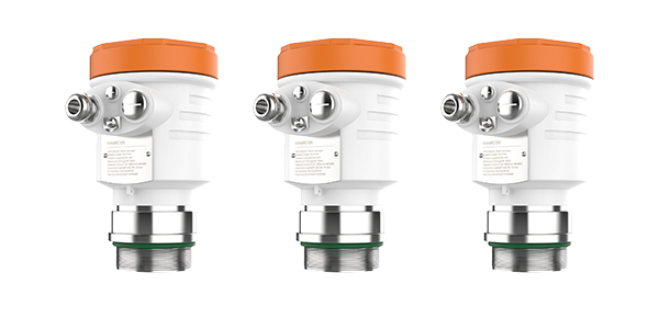
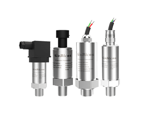
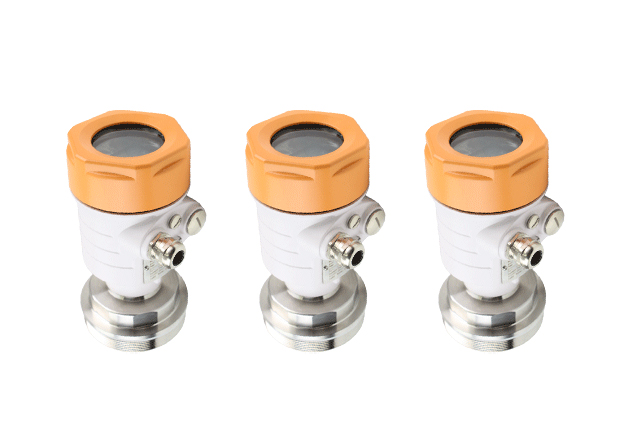
The GPT200 is GAMICOS's most widely used general-purpose pressure transmitter. It employs a diffused silicon pressure sensor as the sensing element and features an integrated all-stainless-steel construction. Suitable for pressure measurement in water, oil, gas, and other media, the GPT200 has a proven track record in HVAC water systems, water supply networks, industrial process control, and many other applications.
Core Operating Principle
The GPT200 utilizes a diffused silicon piezoresistive measurement principle. The measured medium pressure is transmitted through a 316L stainless steel isolation diaphragm to the internal diffused silicon pressure sensor. On this sensor, a Wheatstone bridge—integrated via semiconductor diffusion processes—changes its resistance in proportion to the applied pressure, generating a millivolt-level electrical signal.
This millivolt signal is then processed by the transmitter's dedicated conditioning circuitry: it is first converted to digital via an ADC (Analog-to-Digital Converter), then processed by a digital processor that performs nonlinearity correction, temperature compensation, and digital filtering operations. The final output is a standard 4–20 mA current signal or voltage signal. Compared with traditional analog-only circuit designs, this digital processing path delivers significantly improved measurement accuracy, long-term stability, and noise immunity.
Key Product Features
-
Digital Signal Processing for Superior Noise Immunity: ADC-based digital sampling, combined with digital filtering and differential input technology, effectively suppresses electromagnetic interference generated by variable-frequency drives, pump motors, and other equipment in HVAC plant rooms. This ensures stable, reliable pressure data even in high-EMI environments—directly addressing Pain Point 5 by providing a dependable data source for BMS integration.
-
High-Quality Pressure Chip with Excellent Long-Term Stability: The GPT200 diffuded silicon pressure transmitter uses a high-signal-to-noise-ratio, high-sensitivity pressure-processing chip. During manufacturing, it undergoes laser trimming, digital circuit calibration, and cyclic loading stress-relief processes to significantly minimize long-term drift. Compared with ordinary instruments that require frequent recalibration, the GPT200 offers extended calibration intervals, reducing the maintenance burden described in Pain Point 4.
-
Wide Range Coverage — One Model Fits All Scenarios: The measuring range spans from 0–10 kPa (micro-pressure) up to 100 MPa (high pressure), covering everything from low-pressure terminal branches and medium-pressure main pipes to high-static-pressure applications in tall buildings. Gauge, absolute, and sealed-gauge pressure types are available, reducing the number of spare model variants you need to stock.
-
Damping Structure to Withstand Water Hammer: The pressure inlet can be configured with a damping structure that effectively attenuates instantaneous pressure spikes caused by rapid valve closure and pump start/stop events, preventing permanent sensor damage from water hammer. This directly targets Pain Point 4 by extending service life.
-
Integrated All-Stainless-Steel Construction – Vibration and Weather Resistant: With a fully solid-state design and no moving internal parts, the transmitter offers excellent vibration and shock resistance. It is well-suited for installation environments with persistent vibration, such as pump rooms, and performs reliably over the long term in harsh conditions.
-
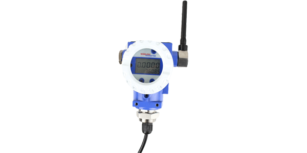
Multiple Output and Electrical Connection Options: Supports 4–20 mA, 0–5 V, 0–10 V, 0.5–4.5 V, and RS485 output formats. Electrical connections are available in Hirschmann, aviation plug, direct cable, and Parker connector styles, making it easy to interface with both existing BMS installations and new control systems—removing the integration barrier identified in Pain Point 5.
Key Specifications
|
Parameter
|
Specification
|
|
Measuring Range
|
-0.1 MPa ~ 0-10 kPa ~ 100 MPa
|
|
Pressure Type
|
Gauge (G) / Absolute (A) / Sealed Gauge (S)
|
|
Accuracy
|
0.5% FS / 0.25% FS / 0.1% FS (optional)
|
|
Output Signal
|
4-20 mA / 0-5 V / 0-10 V / 0.5-4.5 V / RS485 / IIC
|
|
Supply Voltage
|
12-30 VDC / 3-5 V / 5 V
|
|
Isolation Diaphragm
|
316L Stainless Steel
|
|
Electrical Connection
|
Hirschmann / Aviation plug / Direct cable / Parker
|
|
Protection Rating
|
IP65 (IP68 optional)
|
|
Certification
|
CE / RoHS 2.0
|
IV. Customer Case Study: HVAC Chilled Water System Optimization in a Mega-Scale Data Center
Project Background
This data center, located in East China, has a total floor area of 150,000 m² and hosts a major cloud computing business. The cooling system uses a centralized chilled water solution, comprising 12 main branch loops and over 200 terminal precision air conditioning (PAC) units.
Prior to the upgrade, the chilled water network was equipped only with a small number of local dial-type pressure gauges in the plant room; the terminal loops had no pressure monitoring capability whatsoever. Two persistent issues plagued operation: First, hydraulic imbalance resulted in insufficient cooling in certain server rack areas, and multiple equipment overheating incidents led to outages during the year. Second, the chilled water pumps ran continuously at fixed full speed. Annual HVAC energy consumption was approximately 20 million kWh, accounting for 18% of the data center's operating costs—with cooling waste due to hydraulic imbalance estimated at more than 25%.
Core Requirements
-
Acquire real-time pressure distribution data for 12 main loops and over 200 terminal branches
-
Provide reliable pressure feedback signals for variable-frequency control of circulation pumps
-
Enable early detection and rapid localization of pipe blockages and valve faults
-
Achieve full integration with the existing BMS platform for automated closed-loop control
Solution
Hardware Deployment: A total of 280 GPT200 pressure transmitters were deployed across three tiers:
-
Main loop supply/return monitoring (24 points): One measurement point on the supply and return pipe of each of the 12 main branches, used to calculate supply-return differential pressure and assess overall loop resistance.
-
Terminal branch pressure monitoring (200+ points): One measurement point at the inlet of each PAC unit, used to determine whether that unit is receiving its design pressure.
-
Key plant room nodes (dozens of points): Critical locations including pump discharges, header manifolds, and plate heat exchanger inlets/outlets—paired with temperature sensors for cooling capacity calculation.
|
Configuration Item
|
Selection Details
|
|
Product Model
|
GPT200 Diffused Silicon Pressure Transmitter
|
|
Measuring Range
|
0-1.6 MPa (main loops) / 0-1.0 MPa (terminal branches)
|
|
Accuracy
|
0.25% FS
|
|
Output Signal
|
4-20 mA
|
|
Isolation Diaphragm
|
316L Stainless Steel
|
|
Pressure Inlet
|
With damping structure (water hammer protection)
|
|
Quantity Deployed
|
280 units
|
BMS Integration and Automatic Control: All 280 GPT200 transmitters fed their 4–20 mA signals into the existing Honeywell BMS system. The platform used a 3D building model as its base map and displayed pressure data from each point as a real-time heatmap, providing a clear visual overview of the entire network's hydraulic distribution. Three automated control logics were implemented:
-
Variable-frequency pump energy savings: Pressure at the most disadvantaged terminal was used as the control target to dynamically adjust pump frequency. When all terminal pressures remained above the set lower limit, the system automatically reduced frequency—minimizing transport energy while still meeting cooling demand.
-
Early clog warning: The system continuously tracked each branch's pressure baseline. When any branch pressure deviated more than 20% from its historical baseline, it was flagged as a potential filter clog or valve anomaly, and a maintenance work order was automatically pushed with the specific branch identified.
-
Hydraulic balance assisted adjustment: Based on the full-network pressure distribution, the system recommended opening adjustments for each balancing valve, transforming what had been a trial-and-error, experience-dependent process into a one-time data-driven balancing procedure.
Results Achieved
-
Annual energy cost savings: Variable-frequency pump control combined with hydraulic balance optimization reduced HVAC energy costs by 25%, delivering a meaningful improvement in PUE as well.
-
Fault diagnosis time reduced from 2–3 hours to under 10 minutes: The pressure heatmap enabled direct localization of abnormal branches, with location accuracy exceeding 95%. Maintenance response efficiency was fundamentally transformed.
-
Rack inlet temperature stability improved from ±5°C to ±2°C: Hydraulic balancing ensured that each zone received its design flow rate. No cooling-related outages occurred after the upgrade.
-
Investment payback period: 10 months – based on the energy cost savings achieved, the project fully recovered its investment in less than one year.
-
All 280 transmitters operating reliably: The damping structure effectively protected against water hammer caused by valve actuation, with zero instrument failures due to overpressure since commissioning.
V. Summary
The application of the GPT200 in this data center project clearly demonstrates that much of the energy-saving potential in HVAC systems is effectively "locked away" by the inability to see the real-time state of the pipe network. Once pressure data from 280 measurement points was collected continuously, accurately, and integrated into the BMS, the circulation pumps—previously confined to fixed-speed operation—gained the feedback needed for variable-frequency control. Hydraulic balancing, once dependent on guesswork, gained data-driven support. And fault troubleshooting, previously reactive, shifted to proactive early warning.
With its digital signal processing for noise immunity, wide range coverage for selection flexibility, damping structure for extended service life against water hammer, and diverse output interface options for seamless system compatibility, the GPT200 offers a cost-effective yet high-performance solution for large-scale HVAC monitoring deployments. This solution is equally well-suited for the intelligent retrofit of central air-conditioning water systems in commercial complexes, hospitals, hotels, industrial plants, and other types of facilities.